


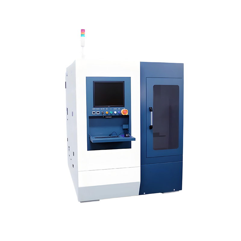
 Cell Laser Scribing Machine")


 Co., Ltd.")
40px
80px
80px
80px
Lecheng Intelligence Technology (Suzhou) Co., Ltd.
Phone
+86-17751173582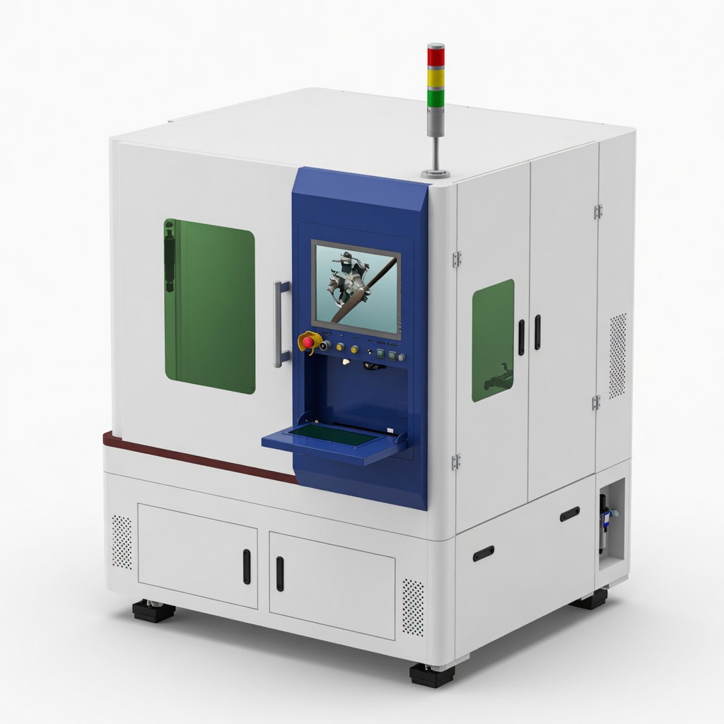
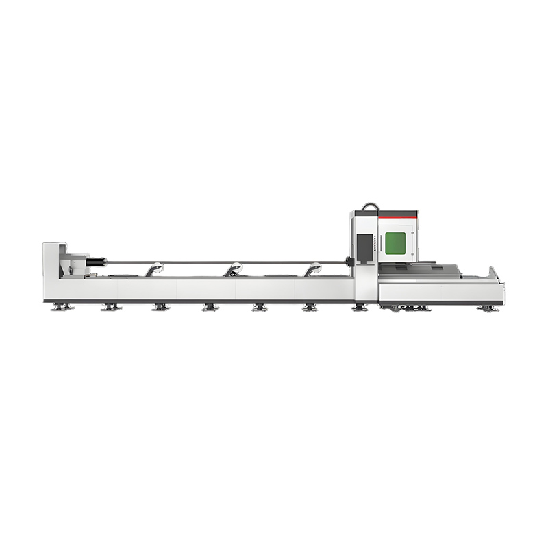
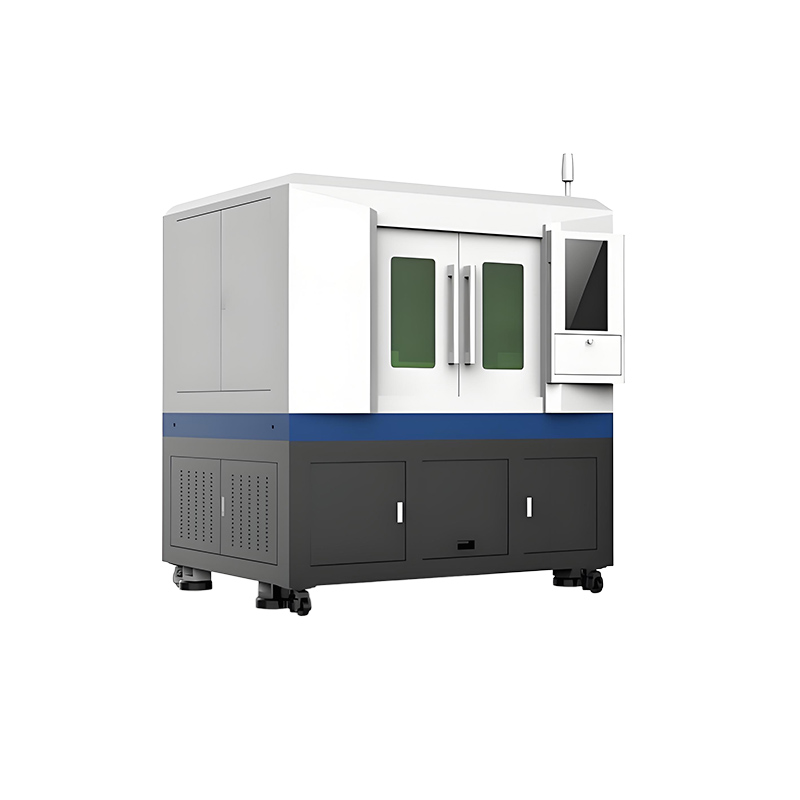
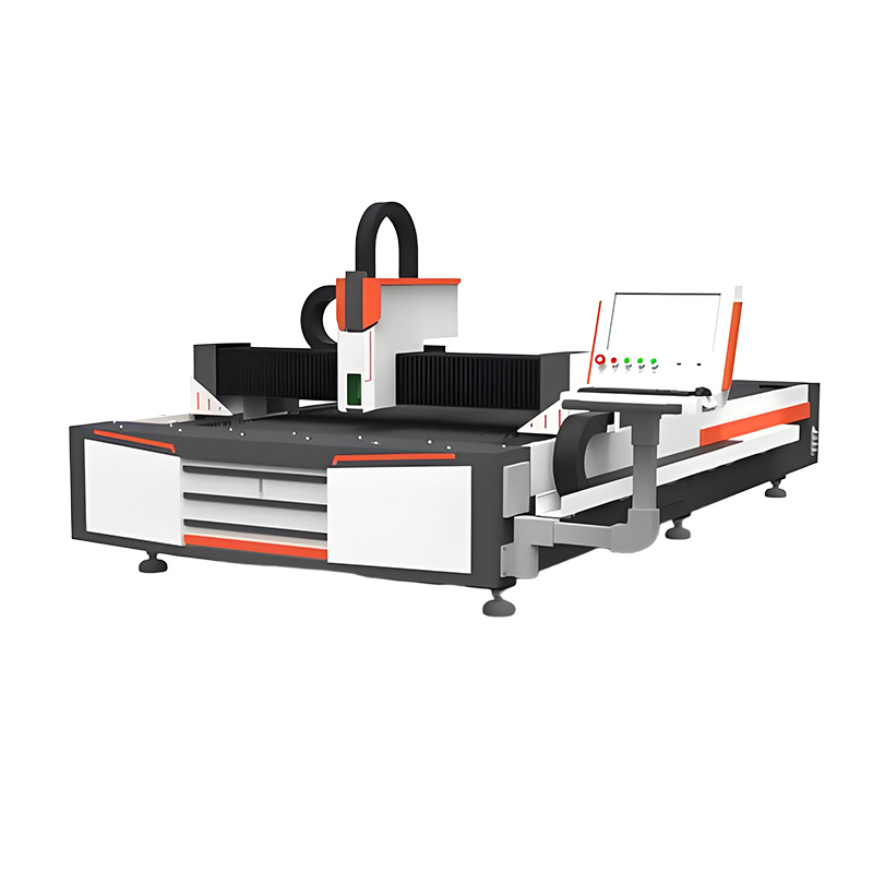
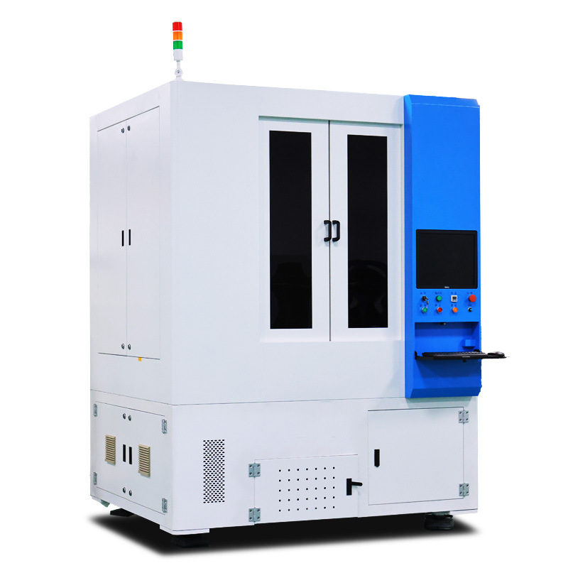
Integrated Cutting + Breaking | Ultra Clean Edge | High Yield Production
The Glass Laser Cutting And Breaking Machine is designed for manufacturers who require high-precision glass processing with stable quality and repeatable results. By integrating an infrared picosecond laser cutting system and a CO₂ laser breaking module into one platform, the machine enables a fully continuous workflow from cutting to separation without manual transfer.
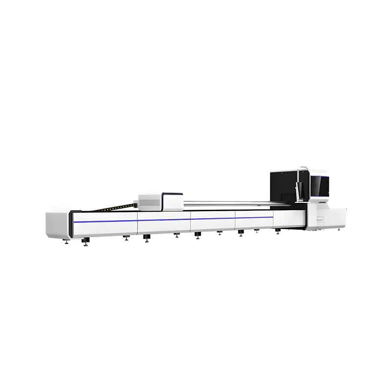
Compared with conventional glass processing methods, this solution delivers cleaner edges, tighter dimensional tolerance, and higher yield, making it ideal for advanced manufacturing applications where consistency matters.


Glass cutting and glass separation are fundamentally different processes:
Creates a controlled modification layer inside the glass
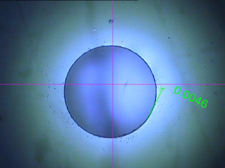
Cutting width: 5–20μm
No thermal damage due to ultra-short pulses
Defines the separation path precisely
Applies localized thermal stress along the cutting path
Enables controlled and clean separation
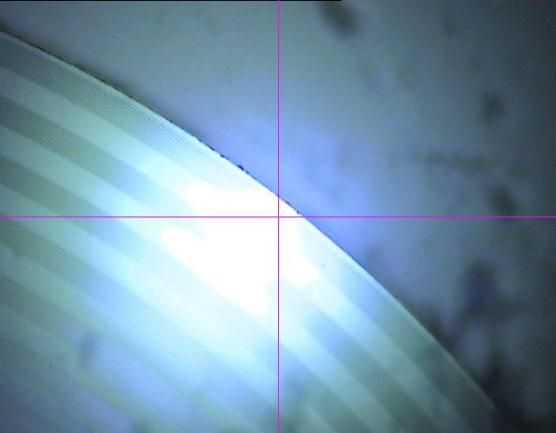
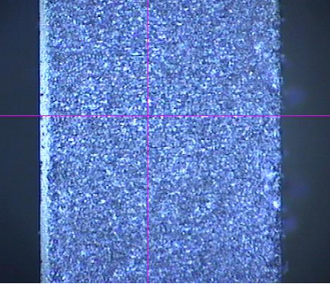
Produces vertical and smooth edges
👉 This dual-laser approach combines the strengths of both systems:
| Method | Limitation | Result |
|---|---|---|
| Picosecond Only | Requires manual breaking | Inconsistent |
| CO₂ Only | Thermal stress & poor edges | Low precision |
| Dual-Laser System | — | Best edge + high yield |
Traditional mechanical cutting introduces:
Micro-cracks up to 100μm depth
Edge chipping 50–200μm
Limited shape flexibility
Picosecond laser technology solves these issues:
Cold ablation (no heat damage)
No mechanical stress
No melt residue
👉 Result:
Up to 300% higher edge strength
No secondary polishing needed
Consistent batch quality
| Parameter | Picosecond Laser | CO₂ Laser |
|---|---|---|
| Power | ≥60 W | >100 W |
| Wavelength | 1064 nm | 10.6 μm |
| Pulse Width | <15 ps | — |
| Beam Quality | M² ≤ 1.4 | M² < 1.3 |
| Stability | <2% | <±5% |
| Lifetime | >20,000 h | >20,000 h |
| Parameter | Value |
|---|---|
| Processing Area | 300 × 300 mm |
| Position Accuracy | ≤ ±10 μm |
| Repeatability | ±2 μm |
| Max Speed | >500 mm/s |
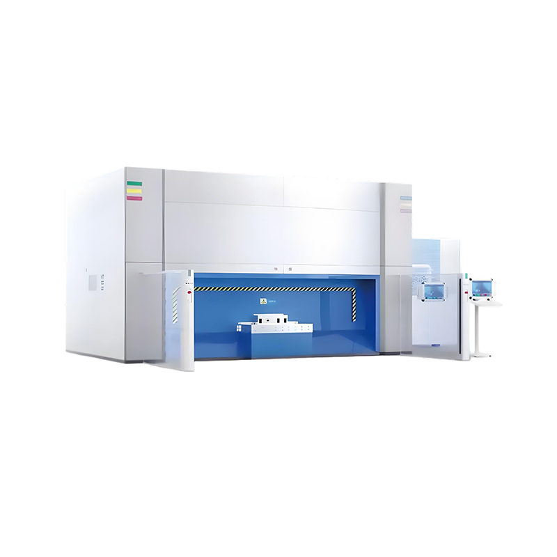
Key Technologies:
Linear motors (no backlash)
High-resolution encoders
Granite base for stability
👉 Ensures long-term precision without degradation
5MP CCD camera
Automatic mark recognition
Alignment accuracy: ±5μm
Positioning time: 2–3 seconds
👉 Enables consistent batch production with minimal operator input
DXF/DWG import
Automatic path optimization
Process database
Multi-layer parameter control
Real-time diagnostics
👉 Operators can reach basic proficiency in 2–3 days
| Parameter | Value |
|---|---|
| Glass Thickness | <10 mm |
| Cutting Speed | ≤500 mm/s |
| Breaking Speed | ≤100 mm/s |
| Cutting Width | 5 μm |
| Edge Chipping | 50–80 μm |
| Yield Rate | 99% |
Thickness: 0.7 mm
Cycle time: 45 sec
Edge chipping: <15 μm
Output: 1500 pcs/day
Thickness: 1.1 mm
Complex shape cutting
Edge strength: 80 MPa
No polishing required
Thickness: 3 mm
Clean edge finish
No post-processing needed
👉 These cases demonstrate real industrial viability
| Parameter | Value |
|---|---|
| Yield | 99% |
| Utilization Rate | 99% |
| Maintenance Time | ≤1 hour |
| MTBF | ≥200 hours |
| Item | Frequency | Time |
|---|---|---|
| Optics Cleaning | 500 hours | 30 min |
| Calibration | Monthly | 1 hour |
| Laser Service | 10,000 hours | Scheduled |
| Software Update | As needed | 15 min |
👉 Annual cost: approx. $2,000–3,000
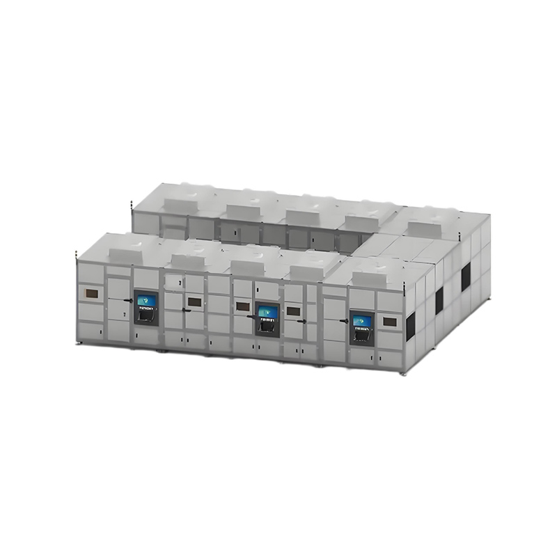
Precision glass cutting
Photovoltaic glass processing
Consumer electronics glass
Automotive glass components
Optical glass parts
Advanced industrial glass manufacturing
If you are looking for:
✔ Cleaner edges
✔ Higher yield
✔ Lower processing cost
✔ Stable long-term production
👉 This machine provides a scalable and reliable solution
40px
80px
80px
80px
Lecheng Intelligence Technology (Suzhou) Co., Ltd.
Phone
+86-17751173582