


40px
80px
80px
80px
Lecheng Intelligent Technology Suzhou
Phone
+86-17751173582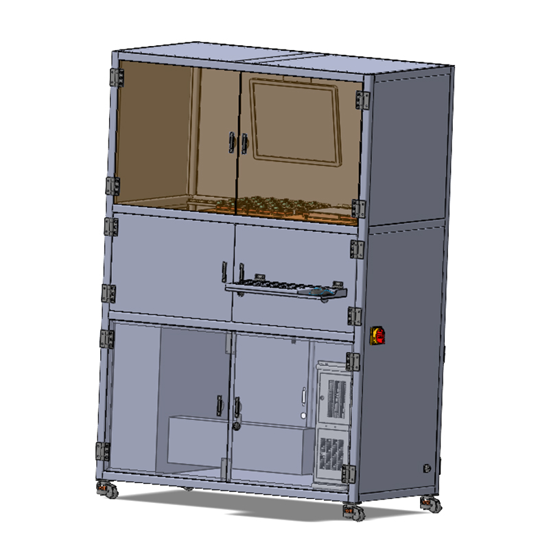
Multi-Channel PV Module Steady-State Testing System is designed for industrial laser processing projects that require stable beam control, process repeatability, and reliable integration with production requirements. For ├ Photovoltaic Solar Testing Equipment selection, buyers should compare material type, processing accuracy, automation level, throughput, maintenance access, and after-sales support before confirming the final equipment configuration.
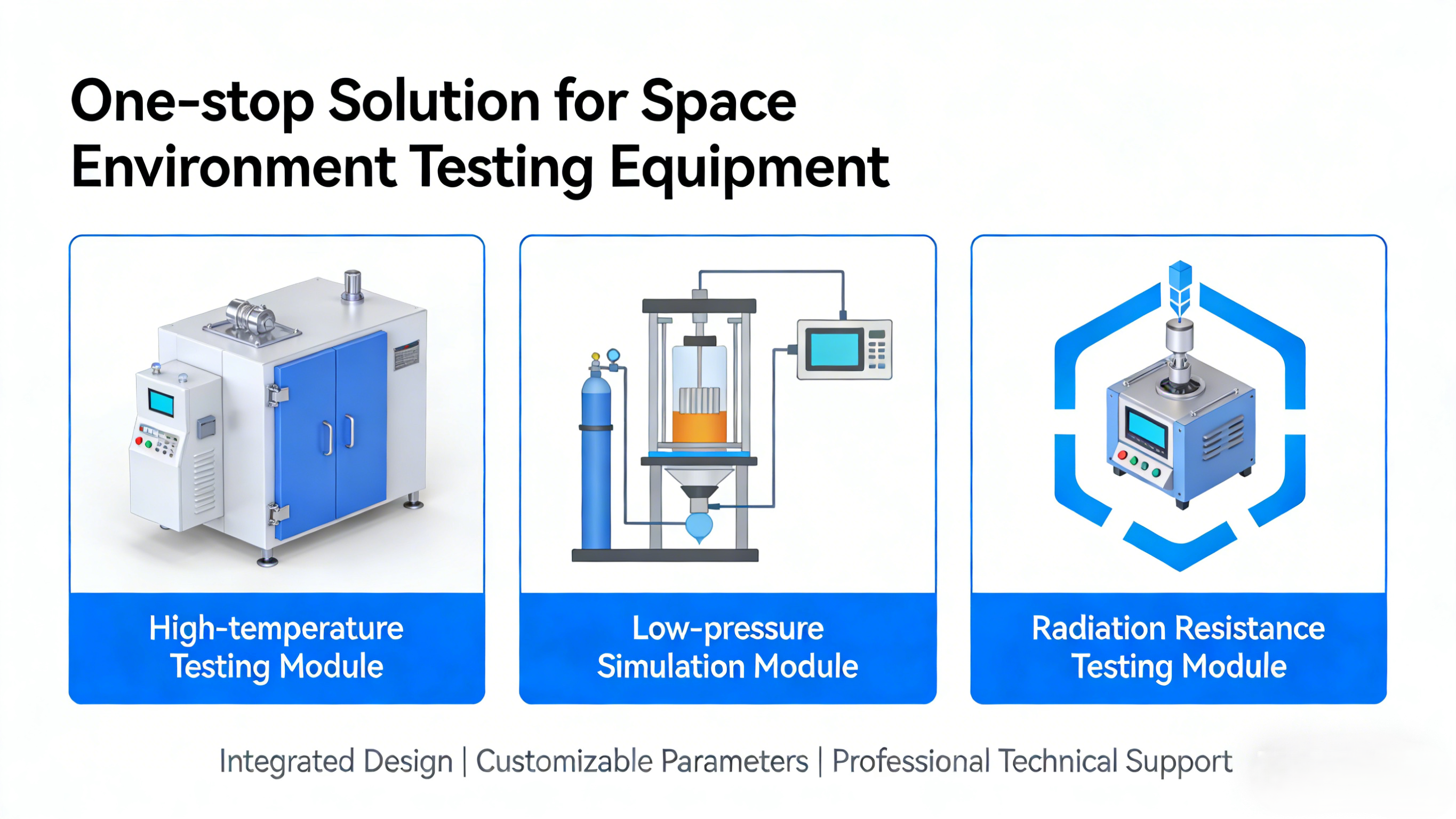
Related laser solutions include LC-SPV-ST-2525 Space Photovoltaic Module Stability Test System, Multi Channel PV Module IV MPPT Steady State Test System, One-Stop Solution for Space Environment Testing Equipment. These internal references help users compare similar systems and move naturally between cleaning, cutting, scribing, marking, welding, and photovoltaic laser equipment pages.
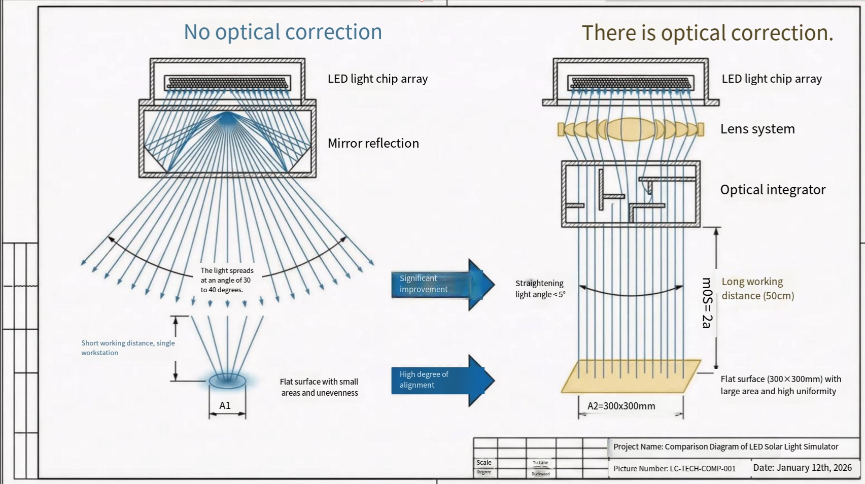
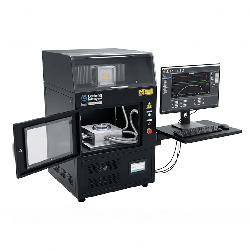
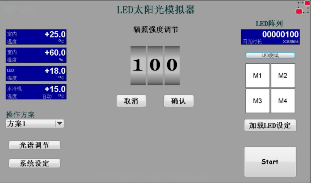
The MCT10-300-20T Multi-Channel PV Module Steady-State Testing System is a high-throughput platform designed to evaluate the illumination stability, temperature reliability, and long-term electrical performance of thin-film, perovskite, and tandem PV modules. Equipped with a 3A-grade LED steady-state solar simulator, independent temperature-controlled channels, and a flexible multi-mode testing platform, the system supports continuous I-V scans, MPPT tracking, and degradation monitoring under precisely controlled conditions.
The Multi-Channel PV Module Steady-State Testing System accommodates module sizes from 50×50 mm to 300×300 mm, covering perovskite small cells, mini-modules, and flexible devices. The simulator supports selectable spectral ranges (300–1100 nm / 300–1200 nm), adjustable irradiance (100–1100 W/m²), and calibrated AM1.5G matching to ensure measurement accuracy.
Module Compatibility Table
| Supported Size | Dimensions (mm) | Substrate Type |
|---|---|---|
| Small Cells | 50×50 | Glass / Flexible |
| Mid-Size | 158×158 | Glass / Flexible |
| Mid-Size | 220×220 | Glass / Flexible |
| Mini-Modules | 300×300 | Glass / Flexible |

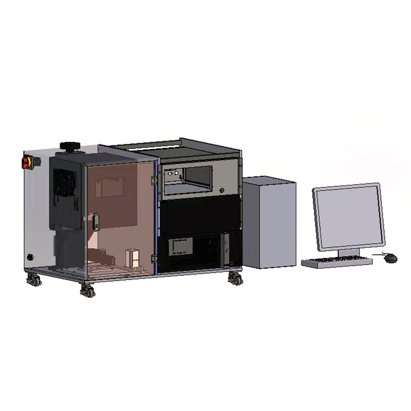
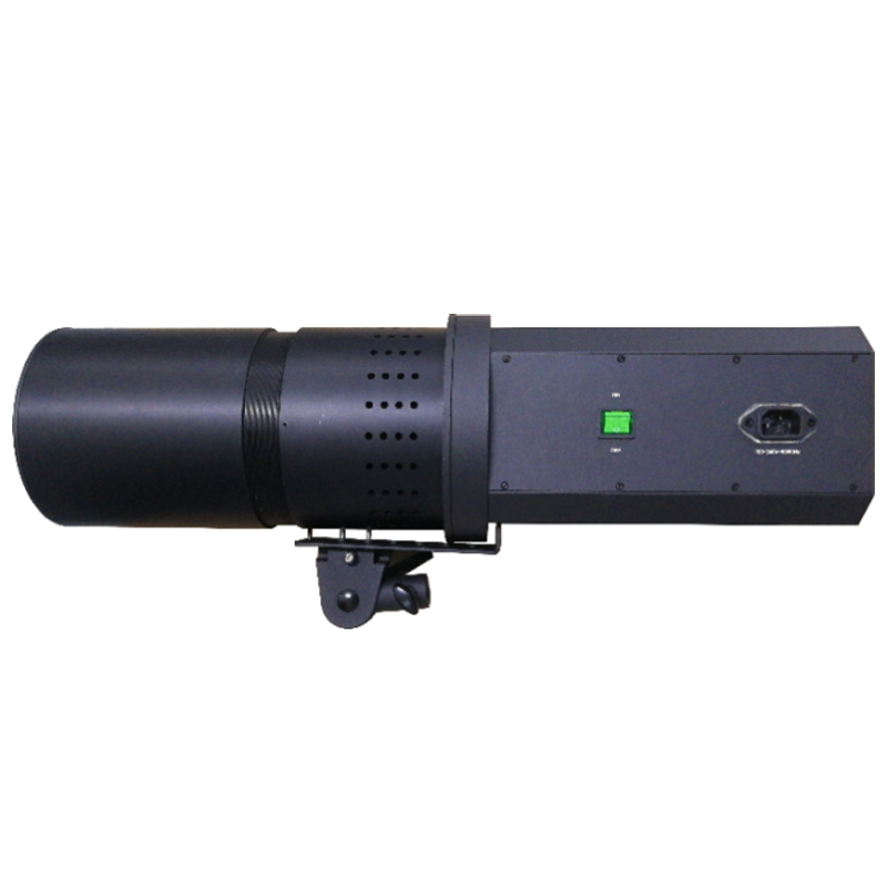
The testing platform integrates high-precision lifting and sliding mechanisms. The lifting module adjusts the light-source height from 10–40 cm with 0.1 cm resolution, while the horizontal sliding platform switches between multi-channel mode (up to 20 channels) and single large-module testing.
The LED steady-state solar simulator delivers industry-standard 3A performance, ensuring accurate optical exposure for long-duration stability studies.
Illumination Performance Table
| Parameter | Specification |
|---|---|
| Spectral Range | 300–1100 / 350–1100 / 300–1200 / 350–1200 nm |
| Irradiance Range | 100–1100 W/m² |
| Uniformity | ≤2% |
| Temporal Instability | ≤±2% |
| Spectral Match | A / A+ |
| Adjustable Distance | 10–40 cm (0.1 cm precision) |
| LED Lifetime | 10,000 h |


The combination of adjustable irradiance, high uniformity, and low time instability ensures that all modules experience consistent, repeatable illumination—an essential condition for light-soaking stability experiments in perovskite and thin-film PV research.
The system incorporates independent electrical source-measure units (SMUs) enabling simultaneous multi-channel testing without interference between channels. Each channel supports individual I-V sweeps, MPPT algorithms, and continuous monitoring of critical PV parameters.
Multi-Channel Electrical Specifications
| Electrical Item | Multi-Channel | Single Channel | Perovskite Single |
|---|---|---|---|
| Voltage Range | 10 V / 18 V | 80 V | 100 V |
| Current Range | 0.5–1 A | 20 A | 1 A |
| Min Voltage Range | 1 V | 10 V | 300 mV |
| Min Current Resolution | 5 μA | 1 mA | 100 nA |
| Accuracy | 0.1% | 0.1 mV / 0.1 mA | ±(0.025%+0.025%FS) |

This wide measurement range supports:
Perovskite pixel-level devices
Tandem mini-modules
High-current crystalline-silicon modules
The system allows each device to operate with its own electrical parameters, enabling realistic performance benchmarking across different material systems.
Each testing position integrates a dedicated heating plate with feedback-controlled thermal regulation that maintains stable and consistent temperatures, ideal for accelerated aging and thermal drift studies.
Temperature System Table
| Parameter | Specification |
|---|---|
| Temperature Range | 25–100°C |
| Stability | ±2°C |
| Feedback Accuracy | 0.1°C |
| Monitoring Method | Patch-type thermocouple |
| Display | Real-time temperature curves |
| Channel Operation | Fully independent |
Unlike shared heating environments, this design ensures that each sample receives identical but isolated thermal conditions—preventing cross-heating effects and improving reliability of data comparison.
The software is fully developed in-house and supports multi-channel control, real-time display, long-term monitoring, and automated data storage.
Software Capability Table
| Function | Description |
|---|---|
| I-V Test Modes | Forward/Reverse Scan, Dynamic IV, 9-Point Fit |
| MPPT Algorithms | Perturb & Observe, Incremental Conductance, Constant Voltage |
| Data Types | Voc, Isc, FF, PCE, Pmax, Imax, Vmax, Rs, Rsh |
| Data Logging | Automatic, timed, per-channel or unified |
| Temperature Display | Real-time curve, multi-channel monitoring |
| Multi-Channel Control | Independent on/off, parameter settings, temperature control |
This allows researchers to run long-duration experiments with minimal manual intervention.
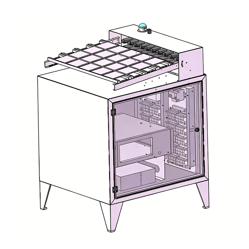
The system's mechanical layout keeps all modules isolated and easy to access while maintaining a dust-resistant and stable testing environment.
Mechanical & Structural Features
| Component | Feature |
|---|---|
| Light Source | Downward-illumination structure |
| Platform | Left-right sliding for mode switching |
| Housing | Dust-proof enclosure |
| Cooling | Forced air circulation |
| Optional | Humidity control module |
Multi-Channel PV Module Steady-State Testing System is suitable for:
Perovskite module long-term light soaking tests
Tandem cell stability verification and MPPT efficiency studies
Thin-film module thermal and optical degradation analysis
High-throughput material screening in research institutions
PV module reliability labs conducting extended aging experiments
| Category | Details |
|---|---|
| Light Source | 3A LED, 100–1100 W/m², A/A+ spectral match |
| Spectrum Range | 300–1200 nm (optional combinations) |
| Module Support | 50×50 / 158×158 / 220×220 / 300×300 mm |
| Temperature System | 25–100°C, ±2°C stability, 0.1°C accuracy |
| Channels | 4 / 8 / 20 channels, independent control |
| Electrical Specs | Up to 100 V & 20 A |
| Software | IV/MPPT/Temperature tracking, auto-save |
| Dimensions | 1200 × 800 × 1800 mm |
| Cooling | Air cooling |
| Optional | Humidity control |
40px
80px
80px
80px
Lecheng Intelligent Technology Suzhou
Phone
+86-17751173582